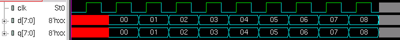
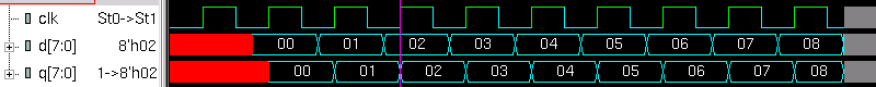
3. Which waveform is the simulation result of Verilog code below?
module dut
(
input clk,
input [7:0] d,
output logic [7:0] q
);
always @*
q = d;
endmodule
module testbench;
logic clk;
logic [7:0] d, q;
dut dut (clk, d, q);
initial
begin
clk = 0;
forever
#10 clk = ! clk;
end
initial
begin
$dumpvars ();
for (int i = 0; i < 10; i++)
begin
@(posedge clk);
#15;
d = i;
end
$finish;
end
endmodule
a)
 b)
b)
 c)
c)
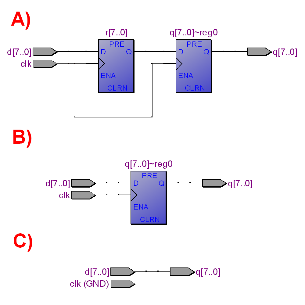
 4. What schematics correspond to Verilog code below?
module dut
(
input clk,
input [7:0] d,
output logic [7:0] q
);
logic [7:0] r;
always @(posedge clk)
begin
r <= d;
q <= r;
end
endmodule
4. What schematics correspond to Verilog code below?
module dut
(
input clk,
input [7:0] d,
output logic [7:0] q
);
logic [7:0] r;
always @(posedge clk)
begin
r <= d;
q <= r;
end
endmodule
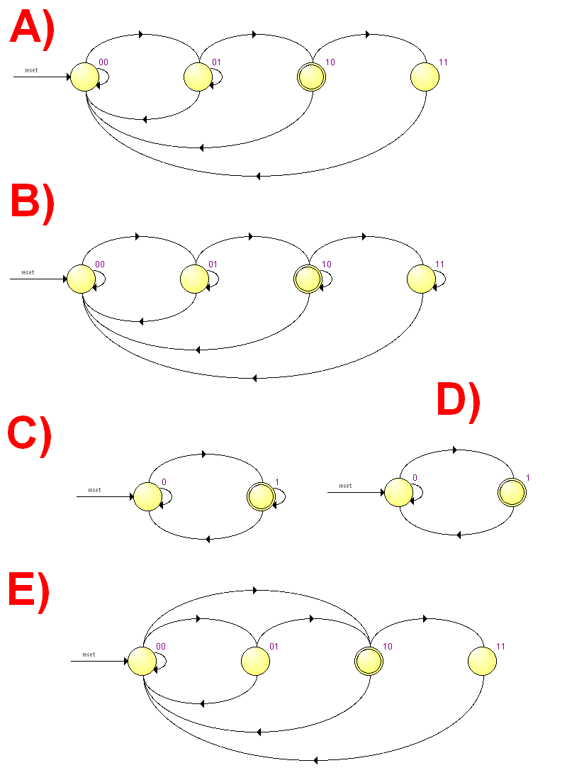
 5. What Finite State Machine (FSM) state diagram correspond to Verilog code below?
module dut
(
input clk,
input resetn,
input a,
output b
);
logic [1:0] state;
always @(posedge clk)
if (! resetn)
state <= 0;
else
case (state)
0: if ( a) state <= 1;
1: if (! a) state <= 2;
2: if ( a) state <= 3;
3: if (! a) state <= 0;
endcase
assign b = (state == 2);
endmodule
5. What Finite State Machine (FSM) state diagram correspond to Verilog code below?
module dut
(
input clk,
input resetn,
input a,
output b
);
logic [1:0] state;
always @(posedge clk)
if (! resetn)
state <= 0;
else
case (state)
0: if ( a) state <= 1;
1: if (! a) state <= 2;
2: if ( a) state <= 3;
3: if (! a) state <= 0;
endcase
assign b = (state == 2);
endmodule